
Interior drainage systems: how they work and why Michigan needs them
An interior drainage system is the engineered infrastructure that collects groundwater entering a basement and routes it to a sump pit for removal.
In Southeast Michigan, clay-dominant soils create constant hydrostatic pressure against foundation walls, and the water table rises and falls sharply with seasonal rain and snowmelt. For that reason, interior drainage systems are the most commonly installed waterproofing solution here and the basis of most residential basement water management.
The main part of an interior drainage system is the French drain: a perimeter channel cut into the basement floor along the wall-floor joint, lined with gravel and fitted with perforated drainage pipe. When hydrostatic pressure forces water through the wall-floor joint or through cracks in the foundation, the French drain intercepts it and channels it through the gravel and pipe to a sump pit. The sump pump then discharges the collected water to a point safely away from the foundation.
Historical development of interior perimeter drainage
Interior perimeter drainage systems evolved from agricultural drainage principles adapted for residential use starting in the mid-20th century. The idea of intercepting subsurface water with a gravel-filled trench and perforated pipe dates to the 19th century, but applying it to basement waterproofing, where the “field” is the interior perimeter of a foundation and the “crop” is the living space above, called for changes to handle the confined geometry, higher hydraulic gradients, and the need to move water mechanically with a sump pump rather than by gravity.
The modern interior drainage system, as practiced in Michigan brings together agricultural drainage engineering, plumbing technology, and building science.
Groundwater hydrology of Southeast Michigan
Southeast Michigan’s groundwater system is a shallow unconfined aquifer held in glacial drift deposits that overlie the bedrock formations of the Michigan Basin. According to USGS Hydrologic Atlas data, the depth to the water table in the Macomb-Oakland-Wayne tri-county area runs from less than 5 feet in low-lying areas near the Clinton River and Rouge River corridors to 15 to 25 feet on morainal uplands.
This shallow water table, paired with the low hydraulic conductivity of the clay-dominant soils, means basement-level groundwater loading builds quickly during a storm and lingers for a long time afterward. That is why interior drainage systems are essential rather than optional for reliable basement water management here.
Mansour’s Innovations designs and installs interior drainage systems fitted to each property’s conditions. The system layout accounts for the basement’s dimensions and shape, where water enters, the foundation type and condition, any interior walls or other obstacles, the best sump pit location, and the discharge route.
A rectangular basement with water entering along two walls needs a different drainage layout than an L-shaped basement taking on water from all sides. A custom design captures water from every active entry point instead of protecting some areas while leaving others exposed.
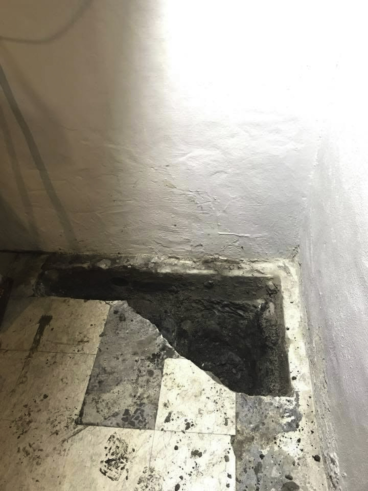
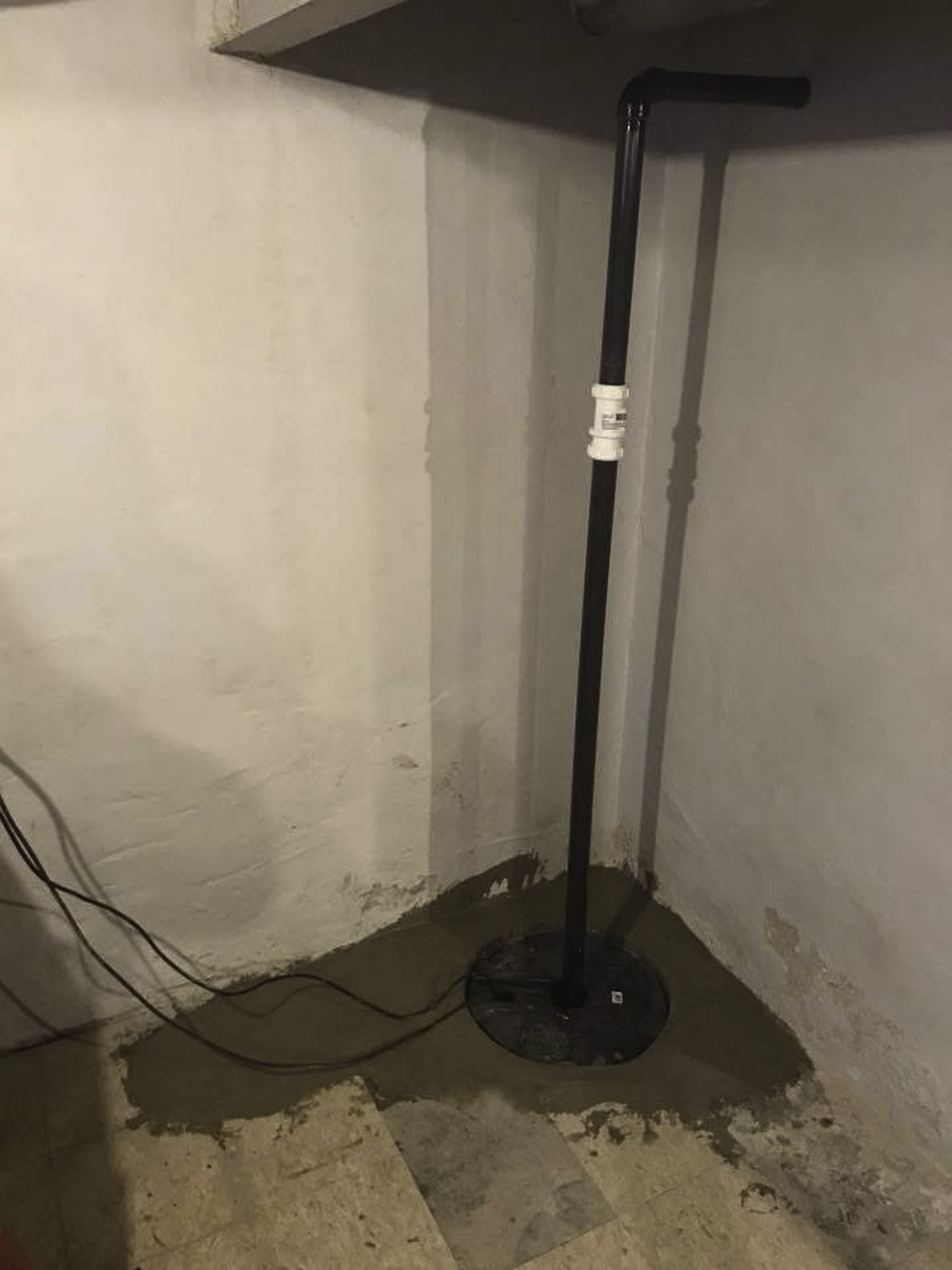
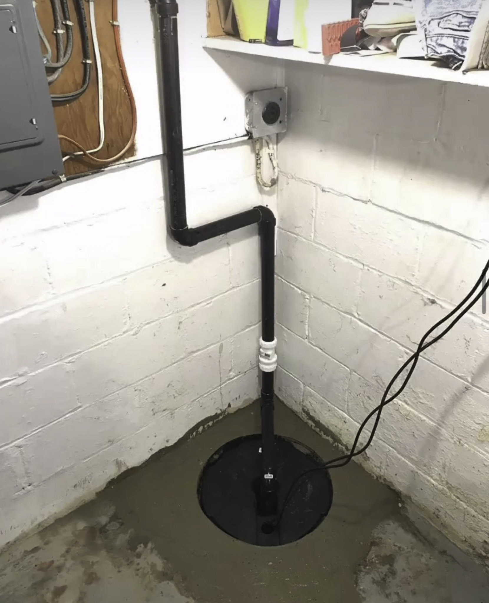
Installation begins with cutting a channel in the concrete floor along the planned drainage route, then excavating to the required depth, placing gravel bedding so water flows properly, installing the perforated drain pipe at the right slope, connecting the drain to a sump pit with correctly sized primary and backup pumps, and restoring the concrete floor. All of the work happens inside the basement, so the exterior of the home, the yard, and the landscaping stay untouched.
Components and performance of interior drainage systems
An interior drainage system performs only as well as its parts are specified and built. The gravel bed has to be sized to filter soil particles while still letting water flow. The drain pipe has to slope correctly so water reaches the sump pit by gravity. The sump pit has to be large enough for the expected water volume without overwhelming the pump. And the backup system has to carry the flow during a power outage.
Mansour’s installs sump pumps from established manufacturers, choosing submersible units for finished basements where noise matters and pedestal units where easy access for service is the priority.
Pump sizing and performance curves
Choosing a sump pump for a residential drainage system means matching the pump’s performance curve to the system’s operating conditions. That curve plots discharge capacity (gallons per minute) against total dynamic head (TDH), which is the sum of static lift (the vertical distance from pit to discharge point), friction losses in the discharge pipe, and any backpressure from check valves.
For a typical Michigan installation with 8 feet of static lift, 20 feet of horizontal discharge, and one check valve, the TDH is roughly 12 to 15 feet. At that operating point, a 1/3 HP submersible pump delivers about 30 to 40 GPM, while a 1/2 HP pump delivers 50 to 65 GPM. Both are adequate for normal conditions, though they leave different capacity margins for a sustained high-water event.
“Here’s our process for interior basement waterproofing: after a free on-site inspection, we cut and remove a narrow trench along the inside base of the foundation walls down to below the footer level. We install perforated drain tile in washed gravel wrapped in filter fabric, add wall flashing along the base of the walls to direct seepage into the drain, install a sump pump with battery backup, pipe the water out below frost depth, and pour fresh concrete over the trench. The system works with Michigan’s soil rather than fighting it: gravity moves water to the pit, the pump moves it out, and the backup handles power outages.”
Vapor barriers go on the foundation walls as part of the same system. The barrier sends wall moisture down to the French drain instead of letting it into the basement air. Together the vapor barrier and the drainage channel form one continuous moisture path from the wall surface to the sump pit, catching both active flow and slow moisture migration.
Most installations finish in two to three days, and Mansour’s flat-rate pricing means the homeowner knows the cost before work begins.
Drainage system maintenance and longevity
How long an interior drainage system lasts comes down to proper installation and regular maintenance. A well-installed French drain system with the right gravel filtration, correct pipe slope, and a properly sized sump pit can work for decades. Still, all mechanical parts need periodic attention. Testing the sump pump monthly by pouring water into the pit confirms that it activates and discharges correctly. Annual professional maintenance covers inspection and testing of every component.
Mansour’s offers ongoing maintenance for the drainage systems it installs. The homeowner has a role too. Listening for unusual pump sounds during operation can catch a mechanical problem before the pump fails outright.
Service life prediction and component replacement scheduling
Service life prediction, set out in ISO 15686 (Buildings and Constructed Assets, Service Life Planning), gives a framework for estimating when waterproofing components will need replacement. The passive parts of a French drain system, the gravel bed, the perforated pipe, and the vapor barrier, have expected service lives of 25 to 50 years under normal conditions, assuming they were specified and installed correctly.
The active mechanical parts wear out sooner: sump pump motors last 7 to 10 years for commercial-grade units, float switches 5 to 8 years, check valves 10 to 15 years, and backup batteries 3 to 5 years. Replacing these on a schedule, rather than waiting for a part to fail in service, sharply cuts the odds of a failure during peak demand.
Michigan homeowners who choose Mansour’s Innovations for interior drainage system installation get a solution built for the persistent groundwater conditions that make Southeast Michigan’s basements among the most moisture-challenged in the country.
Hydraulic engineering principles behind interior drainage
The design and performance of interior basement drainage systems follow basic principles of groundwater hydraulics. Water flow through the gravel bed around the drain pipe is governed by Darcy’s law, the foundational equation of groundwater hydrology that Henry Darcy formulated in 1856. Darcy’s law says the volumetric flow rate through a porous medium is proportional to the hydraulic gradient and the hydraulic conductivity of the medium: Q = KA(dh/dl), where Q is flow rate, K is hydraulic conductivity, A is the cross-sectional area perpendicular to flow, and dh/dl is the hydraulic gradient.
In an interior French drain, the gravel bed is a high-conductivity medium that gives water entering the basement a preferential path. The hydraulic conductivity of washed drainage gravel is typically 1 to 10 cm/s, several orders of magnitude higher than the surrounding concrete or clay soil. That contrast pulls water at the basement perimeter toward the drain pipe instead of letting it pool on the floor or drift into the basement air.
Research on the long-term performance of subsurface drainage systems, published in the Journal of Irrigation and Drainage Engineering, found that the main cause of drainage failure is clogging of the filter medium or the drain pipe by fine soil particles (Stuyt et al., 2005).
In Michigan’s clay-rich soils, that clogging risk is higher because clay particles are extremely fine (less than 2 micrometers across) and can travel in suspension through the pore space of coarser filter media. Using geotextile filter fabric around the drain pipe alongside properly graded washed gravel addresses this by keeping clay from migrating into the system while preserving hydraulic conductivity.
Sizing a sump pump for a residential system means calculating the expected inflow rate during a design storm and making sure the pump’s discharge capacity exceeds that inflow with an adequate safety factor. The inflow rate depends on the basement perimeter length, the hydraulic conductivity of the surrounding soil, the height of the water table above the drainage system, and the effective capture radius of the drain.
For a typical Michigan basement with 120 linear feet of perimeter drain in clay soil and a water table two feet above the drain, the estimated peak inflow during a 10-year recurrence interval storm can run from 5 to 15 gallons per minute. That is well within the capacity of a 1/3 to 1/2 horsepower submersible pump, but it may exceed what smaller or consumer-grade units can handle during a sustained event.
The reliability engineering of sump pump systems uses the same reliability thinking applied to critical infrastructure. The mean time between failures (MTBF) for residential sump pumps varies widely with quality and duty cycle. Commercial-grade submersible pumps from manufacturers like Zoeller and Liberty typically last 7 to 10 years under normal conditions, while budget units may fail within 3 to 5 years. Adding a battery backup pump turns a single-point-of-failure design into a redundant parallel system and raises overall reliability considerably.
References
Darcy, H. (1856). Les fontaines publiques de la ville de Dijon. Dalmont.
Stuyt, L. C. P. M., Dierickx, W., & Martinez Beltran, J. (2005). Materials for subsurface land drainage systems (FAO Irrigation and Drainage Paper No.A 60, Rev.A 1). Food and Agriculture Organization of the United Nations. https://www.fao.org/3/y5754e/y5754e00.htm
ISO. (2011). Buildings and constructed assets, Service life planning (ISO 15686-1:2011). International Organization for Standardization.
